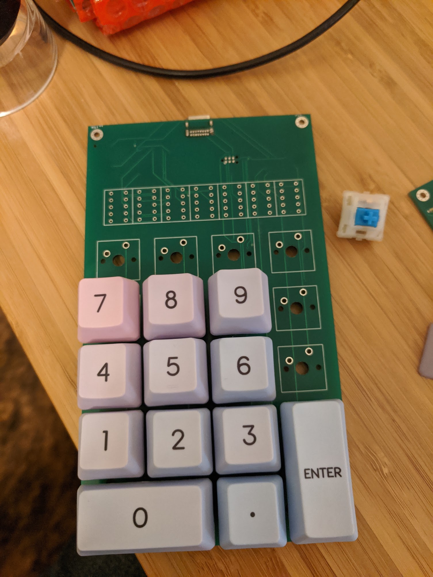
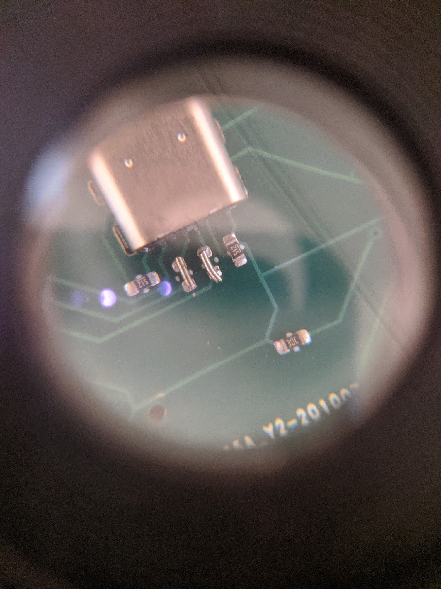
USB-C Connector
Thanks to my fantastic wife/soldering partner, the first board has a USB4085 USB-C connector on it!
Boy are those some tiny pins. Up until now I’ve been powering the board with the TagConnect supplying power, so it’s time to see if the USB-C port can correctly power the board. One trusty USB-A to USB-C cable and… it does!
Now to try a USB-C to USB-C cable. Power negotiation is pretty different for full USB-C so this is a good thing to test as well. Plugging the board into my mac laptop results in… not success. The microcontroller isn’t running. Some probing with my oscilloscope seems to indicate power is being delivered so I’m not sure what the problem is.
After digging around on the internet for a bit and keeping the board powered up over a C-to-C cable, I started to get a sense of some heat coming from the board. One scalded finger later, it seems when powered with a C-to-C cable my microcontroller gets super hot and is now dead. Even worse, I now have zero boards remaining. My choices now are to order more boards, or attempt a microcontroller transplant.
Surgery the First
After ordering some replacement Atmega32U4 microcontrollers and one of these bad boys, it’s time to attempt surgery.
A little bit of Indiana Jones-esque finagling and I’ve managed to swap out the dead microcontroller for a new one and I can program it again! I’m staying away from USB-C to USB-C cables for now, and moving on to see if I can get the device to show up as a USB-HID device.
QMK
QMK is an open source firmware for keyboards. I figured instead of writing my own from scratch it’d be much easier to start with this. I created my subdirectory for my numpad, set up what keys I wanted to do what, tried to compile, and got the following error:
<command-line>:0:16: error: empty filename in #include
keymaps/default/keymap.c:12:24: error: expected '=', ',', ';', 'asm' or '__attribute__' before 'keymaps'
 const uint16_t PROGMEM keymaps[][MATRIX_ROWS][MATRIX_COLS] = {
It turns out that you need to have a .c file that has the same name as your
directory if you want QMK’s build system to work correctly. They don’t seem to
mention this anywhere I could find, but there is a util/new_keyboard.sh which
sets up the directory and file name structure like that. So, if you see the
error above, make sure you have a .c file with the name of your directory.
USB Despair and Saleae to the Rescue
The microcontroller is theoretically all programmed up, but no matter what I do
I see the following from dmesg when I plug the device into my desktop.
[1579839.850659] usb 7-1.1.3: new full-speed USB device number 5 using xhci_hcd
[1579839.850726] usb 7-1.1.3: Device not responding to setup address.
[1579840.058745] usb 7-1.1.3: Device not responding to setup address.
[1579840.266659] usb 7-1.1.3: device not accepting address 5, error -71
[1579840.346664] usb 7-1.1.3: new full-speed USB device number 6 using xhci_hcd
[1579840.346730] usb 7-1.1.3: Device not responding to setup address.
[1579840.554720] usb 7-1.1.3: Device not responding to setup address.
[1579840.762659] usb 7-1.1.3: device not accepting address 6, error -71
[1579840.762706] usb 7-1.1-port3: unable to enumerate USB device
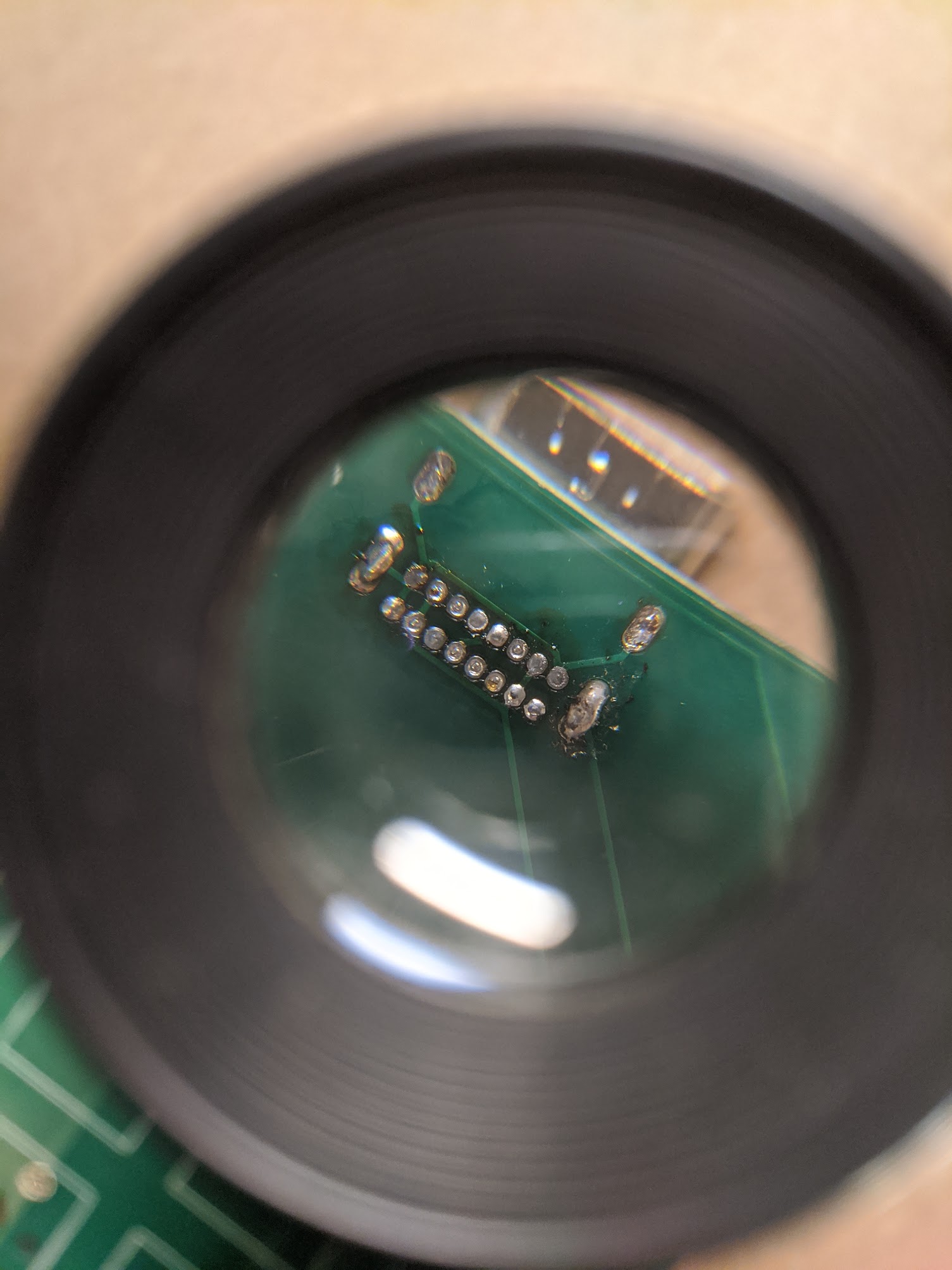
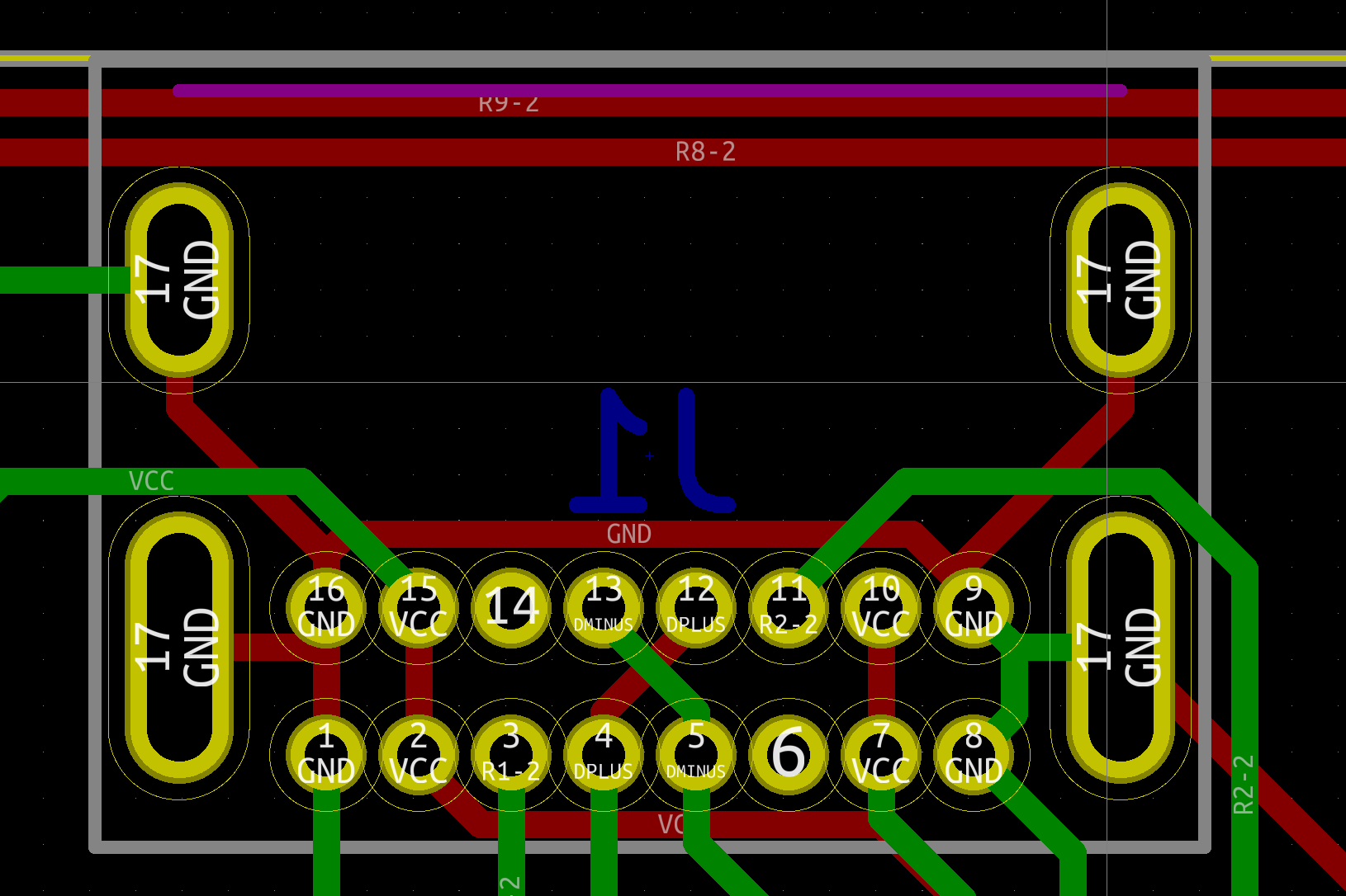
The first thing I decided to check was that I’ve actually connected the USB pins to the right pins on the connector. This was made a little more exciting because the schematic for the connector shows it from the top with the connector facing south.
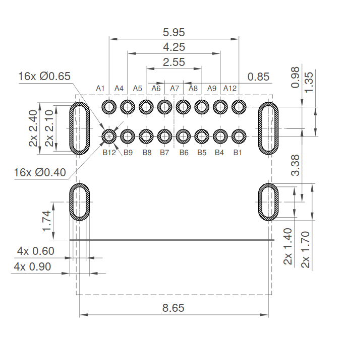
And in my schematic the connector is viewed from the bottom and facing north.
After doing a 180 degree rotation and flip in my head over and over, as well as checking how other devices have used the same connector, I was unable to find any problems with the USB connector.
Next I checked all the pins on my microcontroller were connected to the right things and had the right values. D+ at 3.3 volts? Check. UCap connected properly? Check. Everything is connected right. Still I checked and re-checked about 10 times, never coming up with any visible mistakes.
I tried flashing test USB programs from V-USB and LUFA but neither of those made any difference.
I spent about 5 days checking, re-checking, and reading as many internet posts as I could find and nothing seemed to give me any hint as to what could be wrong.
Next I took out my logic analyzer from Saleae. This is a super cool little device that hooks up to your computer and can sample and decode analog and digital signals.

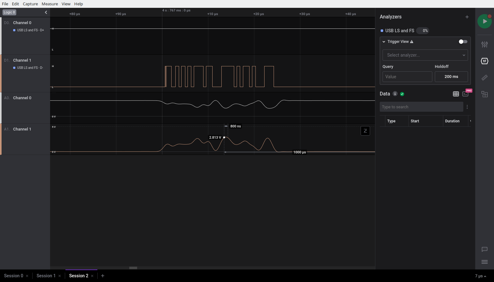
I downloaded the new V2 version of their software and sampled the D+ and D- lines. It looks like data is being sent back and forth appropriately when I plug in my board.
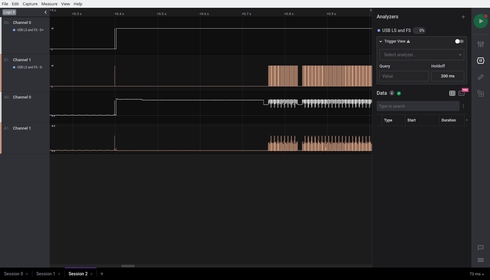
One thing I noticed when zooming in though was that D+ and D+ aren’t exactly the robust signals I’d imagined. D+ seemed to hang out mostly around 3.3V and D- barely made it to 3V.
This sparked an idea. Could I have put the wrong resistors on the USB data lines? The USB spec calls for 22 Ohm resistors. The way that I generate the BOM for the manufacturer involves generating a file of part numbers. Not the most human-readable format:
Part{Type: "Resistor", Value: "22"}:   "C4190",
Part{Type: "Resistor", Value: "1k"}:   "C21190",
Part{Type: "Resistor", Value: "5.1k"}: "C23186",
Part{Type: "Resistor", Value: "10k"}:  "C25804",
Part{Type: "Resistor", Value: "20k"}:  "C4184",
Part{Type: "Resistor", Value: "100k"}: "C25803",
I decided to just double check what part number C4190 is, and… IT’S A 2200 Ohm resistor. When selecting part numbers, I typed in 22, and apparently 2.2k also matches the search and I didn’t notice! Indeed if I look at the resistors they say “222” on them, which mean 22 followed by 2 zeros = 2200.
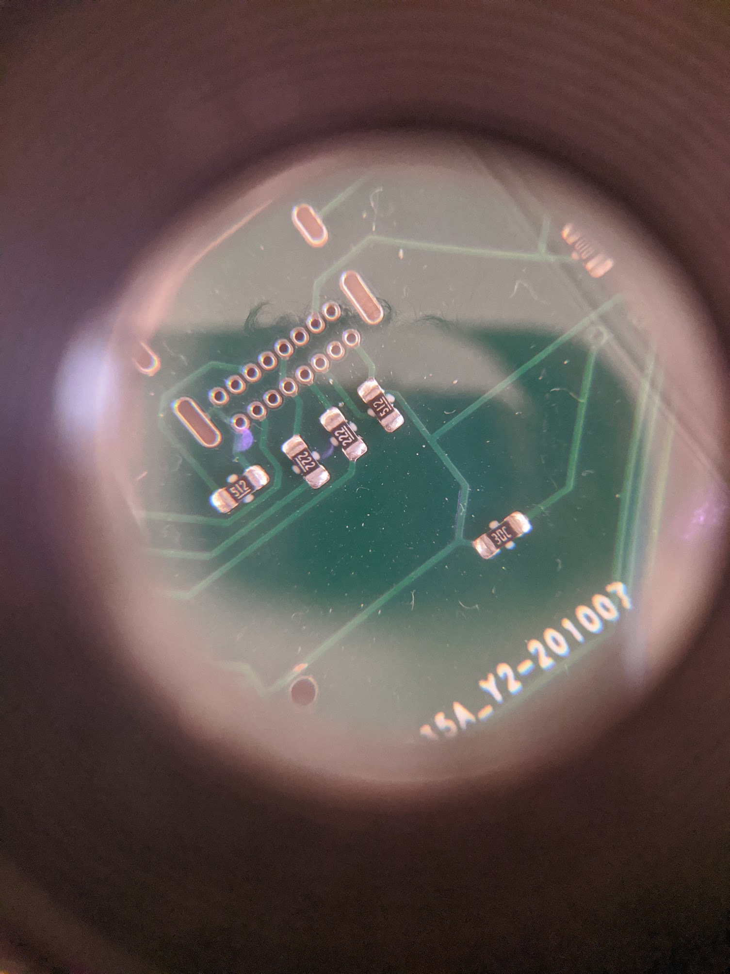
Finally, an actual problem! I don’t have any 22 Ohm resistors hanging around though. I have 220 Ohms, but putting 10 of those in parallel seems ridiculous. After a bit of research it seems that having no resistors at all can work, so let’s try that.
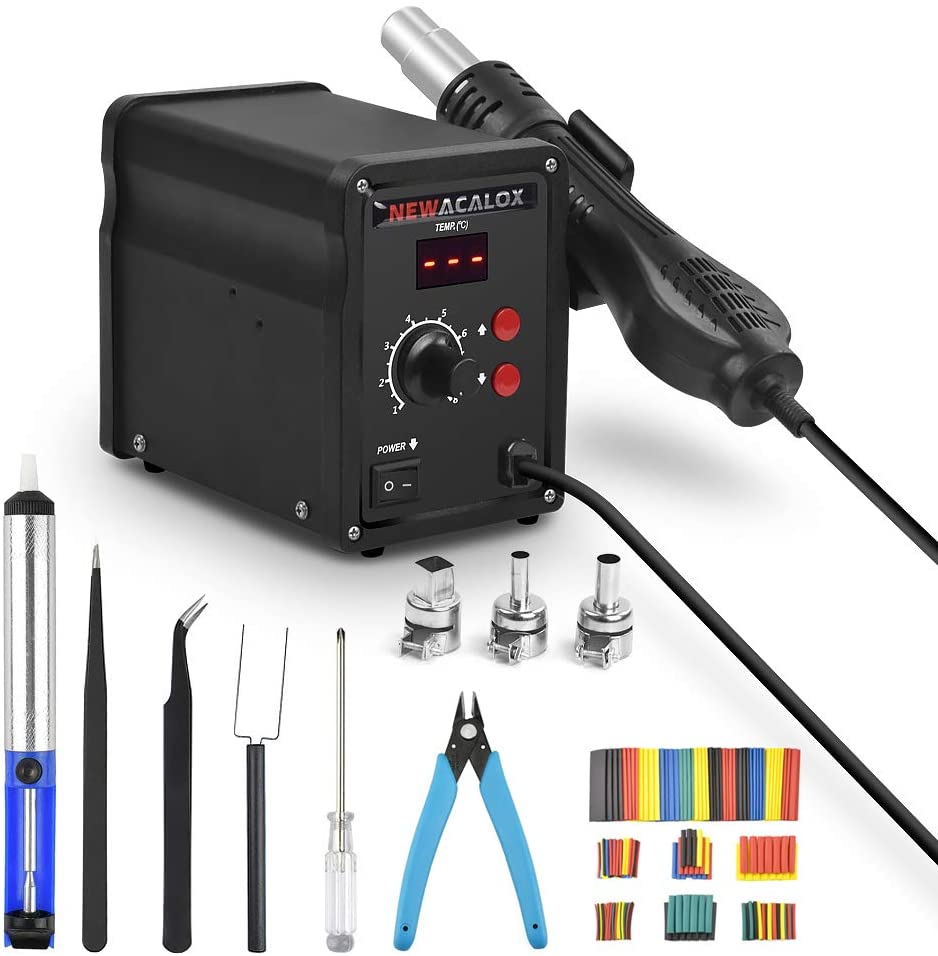
Surgery the Second
Using my new handy heat gun, I removed the 2.2k resistors, snipped off some bits of through-hole resistor legs, and soldered them back on.
After letting it cool down, I plugged it into my computer and… SUCCESS!!!!
[1589525.863330] usb 1-6: new full-speed USB device number 9 using xhci_hcd
[1589526.030525] usb 1-6: New USB device found, idVendor=feed, idProduct=0000, bcdDevice= 0.01
[1589526.030527] usb 1-6: New USB device strings: Mfr=1, Product=2, SerialNumber=3
[1589526.030528] usb 1-6: Product: NUMPAD
[1589526.030529] usb 1-6: Manufacturer: GABE
[1589526.030530] usb 1-6: SerialNumber: 0
Behold, the first hardware!