First Hardware Test
It’s time to bite the bullet and actually get some hardware made. I need to test three things.
- Does my software-based hardware description language generate working circuit boards, and have I used it correctly to create a functioning keyboard?
- Is the spacing and layout of the keys on the board comfortable?
- Can I correctly instruct the manufacturer to put all of the capacitors, resistors, diodes, and other components on the board in the right place and orientation.
Numpad
For my first design I wanted to start with a numpad. If it ends up not working at all then I haven’t wasted 5 whole keyboard’s worth of PCB fiberglass, and if it somehow does work on the first try then I can actually use it! I began with this design:
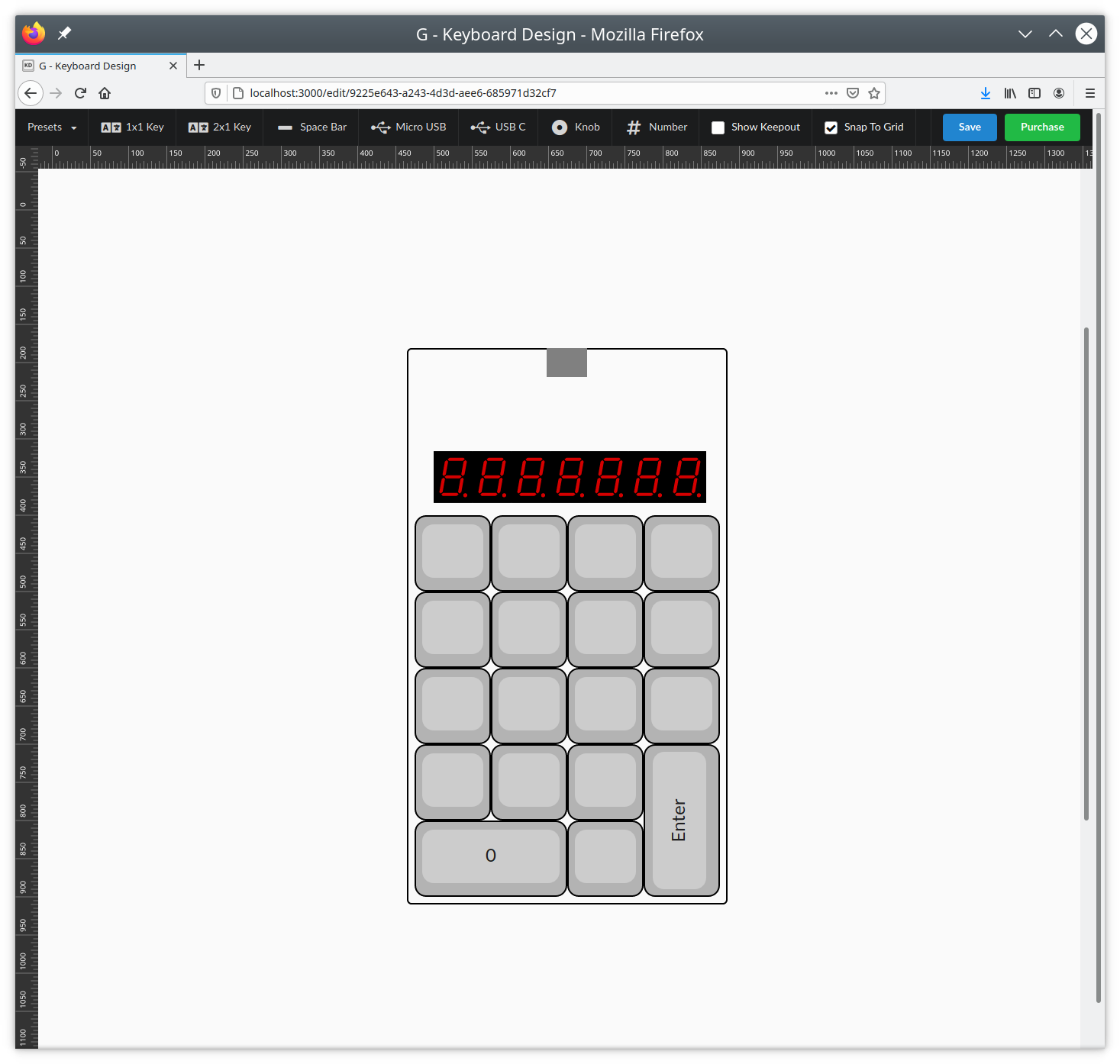
Please excuse the partially filled in numbers and “enter” key. I threw on a big digit display so I could test out if the footprint for the displays is correct, and whether or not my driver circuit works. I’ve never used the IS31FL3733 before, so getting a little practice with it sounded good.
First Boards
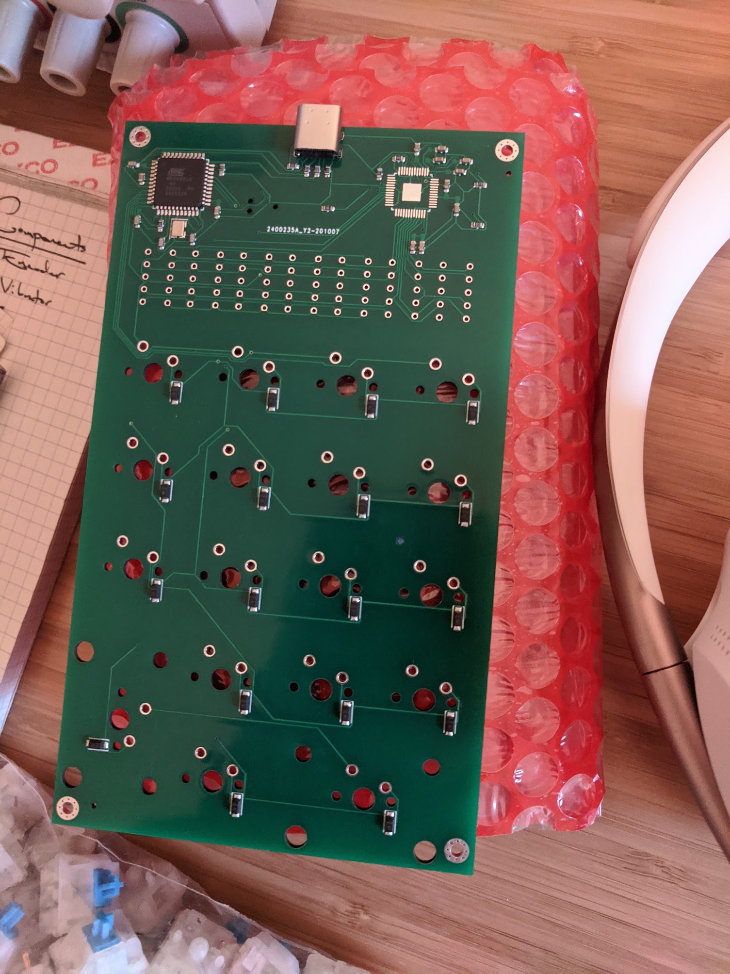
The first boards are back! After excitedly looking over my first fab house assembled boards, I tried fitting a few components. Key switches are quite snug but they fit. USB-C jack fits but its pins short and don’t quite make it all the way through the board. I guess we’ll find out if that’s a problem. 7-segment displays… wow did I mess up that footprint. The holes are way too close together, so either I won’t be testing LED driving on this board, or I’ll wire one up with jumper wires.
Does the Microcontroller Work?
I dug out my USBTinyISP and installed avrdude, avr-gcc, and the other related
AVR build tools. After figuring out how to affix the new TagConnect connector I
tried probing with avrdude -v -p m32u4 -c usbtiny and… nothing. Error.
I checked to see if the oscillator was oscillating, and it was maybe a little?
But not really. I checked to see if the parts of the board that should be
getting power are, and some are? Sort of? In general, not good signs.
After 15 minutes of staring at the schematic to see what I could have done wrong, I realized I had the tag connect plugged into the USBTiny backwards! After flipping it around, avrdude can see the atmega32u4, and I can program the board! HUGE SUCCESS SO FAR.
By default the atmega32u4 comes with the 8x slow-down fuse bit enabled. I’m not quite sure what happened, but in trying to fix that I ended up setting random garbage into all the fuse bits and now the board is bricked. If I had a high voltage programmer I’m supposedly able to fix this, but I don’t. Thankfully I had two boards assembled of the five, and with a lot more care this time around, I have the board up and toggling pins at full speed! In hindsight it would have been good to have all 5 boards assembled for an extra $10, but I assumed the boards wouldn’t work at all and I didn’t want to waste the components.
USB-C
Ugh, USB-C. It seems that soldering USB-C connectors at home is not for the faint of heart. Because I’m only planning to run USB 2.0 I don’t need all the pins on the full connector, so I found this through-hole connector (USB 4085) and will attempt to solder that. After that it’s time to test if USB power and connectivity works. Until next time!