For the synthesizer I’m building, I want to have a series of touch sensitive buttons for the keyboard keys. I like the idea of using touch sensitive buttons because it results in fewer components to buy which keeps the price down, and fewer pieces of hardware that can break.
This post shows how to create complex shaped components for use on your PCB using KiCad.
The Goal
Usually on PCBs, the only color options are the silkscreen color (normally white), and the soldermask color (usually green). Recently though there has been a burgeoning PCB Art scene that’s produced some amazing looking PCBs by making use of the manufacturing process to enable up to 4 colors! There’s the bare board, the copper layer, the soldermask layer, and the silkscreen layer. Andrew Sowa seems to be able to get 5 colors but I have no idea how. What is the black on his boards? Is it soldermask with no copper underneath? I’m stumped. Drop me a line if you know!
I spent some time in Inkscape and mocked up the following drawing of an octave of the keyboard:

The black lines represent silkscreen on the PCB (usually printed in white) and the gold color represents exposed copper which should be nice and shiny.
Prerequisites
- Install KiCad:
sudo apt install kicad. - Install Inkscape:
sudo apt install inkscape. - Download SVG2Shenzen, unzip it,
and install the contents. You’ll want to put the unzipped files into the
“User Extensions” folder. You can find out the location of that folder by
opening Inkscape and going to the Edit Menu > Settings > System. On Linux
it’s
$HOME/.config/inkscape/extensions.
Creating the Footprint
Open up Inkscape and look under the “Extensions” menu for an item named “Svg2Shenzen”. If you don’t see it and you’ve followed the instructions in the prerequisites section, try restarting Inkscape.
Under the “Svg2Shenzen” menu, select “1. Prepare Document…” and choose the size of your sheet. This just needs to be big enough to hold your drawing so you don’t have to be exact.
Open up the Inkscape layers palette and you should see the following layers:
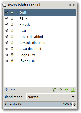
The layers represent the following:
- Drill: This layer indicate that holes should be drilled into the PCB. For this keyboard component I don’t want any holes.
- F.Silk: This layer indicates where silkscreen should be drawn on the front of the PCB.
- F.Mask: This layer is a bit backwards from the rest since it represents where you don’t want soldermask to be placed. It’s a soldermask mask. As with F.Silk, the ‘F’ refers to “Front” a.k.a. the top of the PCB.
- F.Cu: This layer indicates where you want exposed copper to show through. If you need to solder something to your PCB, this is where you indicate that so that the copper shows through. You nearly always want to have the same thing on your F.Mask and F.Cu layer, otherwise the copper will be hidden behind the soldermask and you won’t be able to solder something onto it.
- B.Silk, B.Mask, B.Cu: These are the same as the previous layers except for the back a.k.a. bottom side of the PCB.
- Edge.Cuts: Svg2Shenzen can be used to create artistic (or just complicated) PCB outlines as well. I don’t need that in this case because I’m designing a component on the board, not the shape of the board itself.
Two important notes:
- Make sure to remove “-disabled” from the names of any layers you end up using.
- Svg2Shenzen does not work well if any content on your layers has a color besides black. Make it all black!
Now that the layers are all set up, it’s time to draw. If you want to see my
final Inkscape file, you can grab it here:

Finally, in the “Extensions” > “Svg2Shenzen” menu, select “02. Export Kicad…”
and save the exported file. It will generate a file with a .kicad_mod
suffix.
Importing into KiCad
Now that we’ve created our .kicod_mod file describing the contents we want on
the layers of the PCB, it’s time to show KiCad how to use it. We’ll create a
new library to hold our footprint. If you already have a library for custom
footprints you can skip that part.
Creating the Footprint
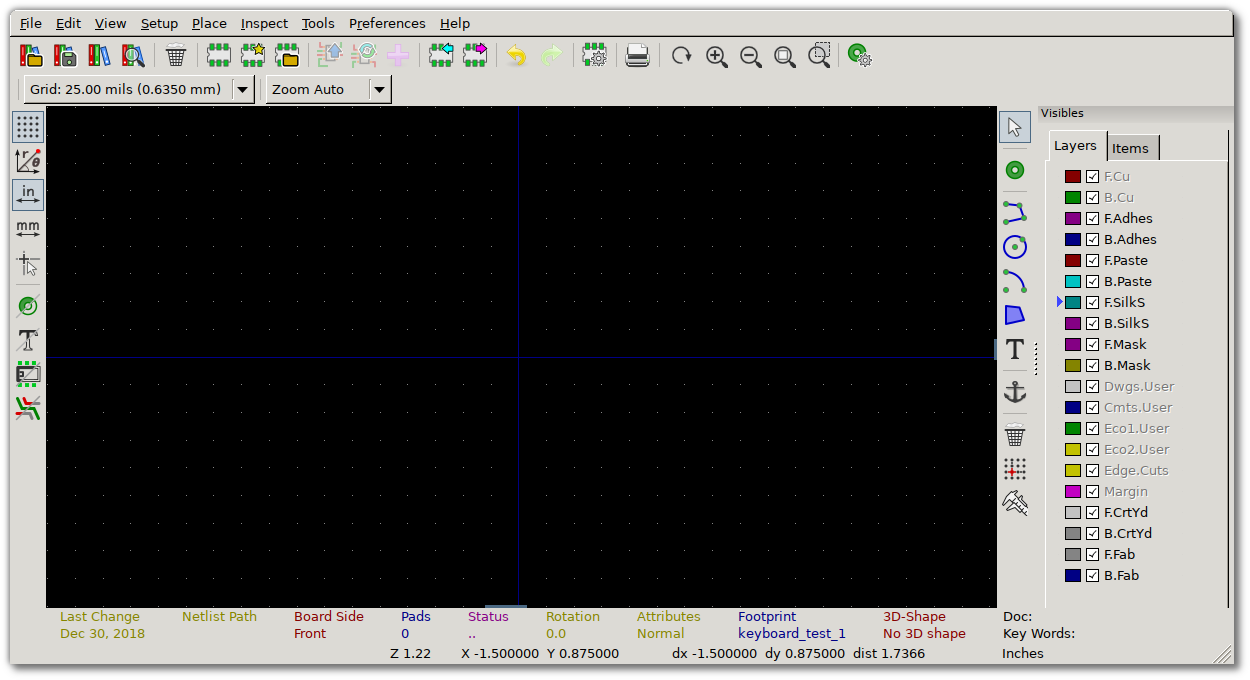
Open up KiCad and click on the Footprint Editor button which is the fourth one from the left and looks like a computer chip with 3 legs on the top and bottom:
You should be presented with the Footprint Editor screen:
The firt step is to go to “File” > “New Footprint…” to create an empty footprint. Only after doing this can you click on the icon in the top bar of the three books to create a new library:

Now that we have our new library in which to place our custom footprint, go to
“File” > “Import” > “Footprint from KiCad File” and select your .kicad_mod
file that you exported from Inkscape in the first part of this post. When
that’s done you should see something like the following:
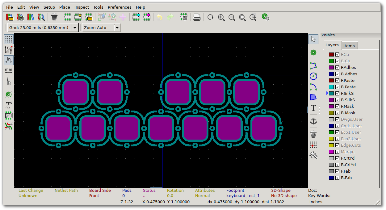
At this point we have our footprint imported and we could technically use it by routing traces to each of the purple spots. However, KiCad has a concept of “pads” which represent electrical connectivity of a footprint. KiCad will make sure that the right traces go to the right pads and can alert you if you haven’t done so. So, as our final step we’ll turn each of the copper portions of each key into a pad.
Click on the “Add Pad” button:  and then
click on the the first key of the keyboard. A tiny dot should appear under
where you clicked. Hover the mouse over it and hit the ‘e’ key to edit its
properties. This should bring up the following window:
and then
click on the the first key of the keyboard. A tiny dot should appear under
where you clicked. Hover the mouse over it and hit the ‘e’ key to edit its
properties. This should bring up the following window:
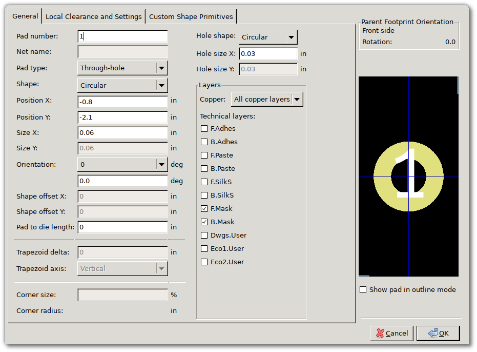
The default pad that gets created is a through-hole pad. In this case we don’t want the pad to create a hole in the board, so change “Pad type” to “SMD” and hit OK.
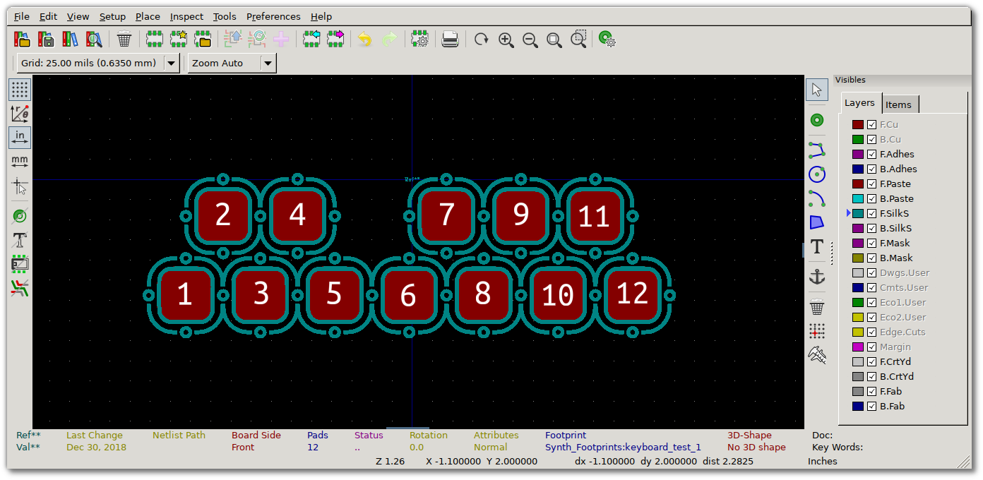
What we have now is a pad that’s sitting in the middle of what we want to be the actual pad. This would also work, except that when you route traces on the PCB, KiCad will make sure it doesn’t route traces over pads. If we left things as they are now, when routing traces KiCad would be happy for them to go through the big copper fills for each key. To fix this we can designate the entire copper region of each note to be the pad.
To create our custom shaped pad, select both the pad we just added as well as the rounded rectangle for the first key. Right click and select “Create pad from selected shapes” and kaboom! We now have a pad that’s the entire shape of the copper we designed for that key. Repeat this for each of the 12 keys and you end up with this:
Results
Now when assigning footprints to components in your schematic you can choose your brand new footprint, add it to your PCB, and kaboom!
